Getting Started with your WebFPGA Kit
21 Aug 2019, Mick Jacobs, Ryan Jacobs
After months of anxious anticipation, a neatly packaged white parcel arrives at your doorstep. Oh what’s that? “WebFPGA”, it reads.
Today, you have received your WebFPGA kit. Oh boy.
After connecting the slim, red PCB to your computer’s USB port, you witness an orange, blinking LED. Seems like once a second.
Pressing the white on-board button seems to change the rate of blinking. That’s interesting, you note. But it’s time to move on to bigger and better things.
You’re ready to begin building your own applications.
Hopefully that wasn’t too melodramatic. But we’re excited. And we hope that you’re excited too! Let’s run some examples before you get ahead of yourself.
First things first
If you are running on Linux, you need to install a udev rule in order
for the user space to have read/write permissions to the board (linux-udev-rules).
Make sure to reload the rules with sudo udevadm control --reload-rules && sudo udevadm
trigger.
Test out some code
Even if you plan on using offline tools, the Web IDE is a convenient home to example code. You can use it to ensure that your hardware is functioning properly. Open the Web IDE using Google Chrome or Opera: beta.webfpga.io
Easily, the most eye-catching example is the on-board Neopixel RGB LED.
Load the example named WF_neopixelx1_fading_demo.v and click Run Synthesis.
Wait for up to two minutes for synthesis to complete. After the console
outputs Bitstream ready, click Flash Device.
(Note: The x1 in the filename indicates that the code controls a single
Neopixel LED. x8 refers to the Neopixel peripheral strip.)
Now the board should pulsing with a pleasing RGB pattern.
Branching out
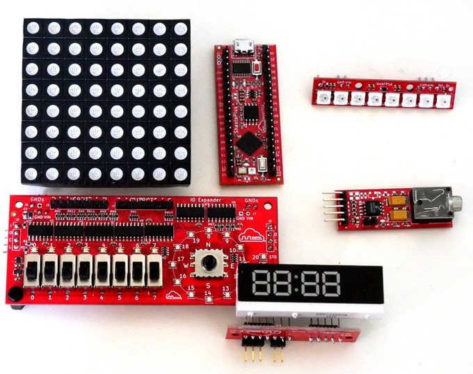
After you have the on-board examples running, it’s time to move on to the kit peripherals.
We will outline connecting the modules together using a breadboard. There are other methods, but breadboards are visually simple and require no jumper wires.

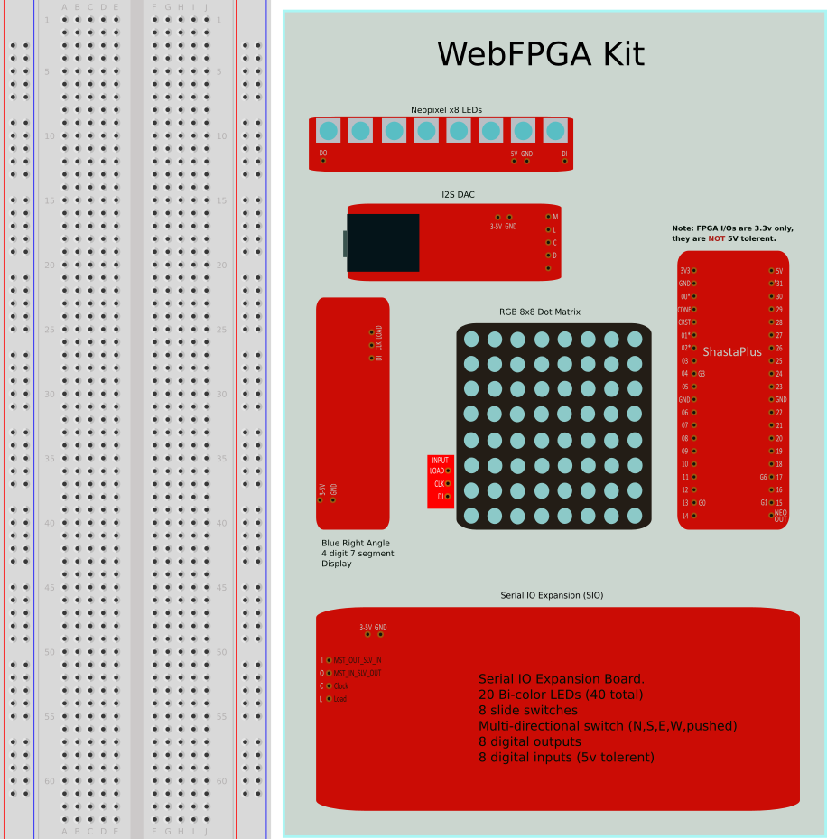
Each peripheral in your kit will need male headers soldered on to allow for insertion into the breadboard. But be careful! You don’t need to solder pins to every single pin — in fact, that will actually make insertion more difficult.
Use the above image as a reference to which pins you should solder.
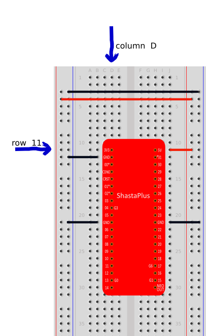
After you’ve soldered those modules, insert the main device into the breadboard,
aligning the top-left pin into Row 11 and Column D.

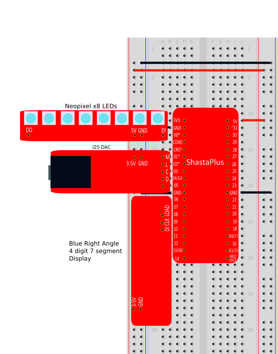
Then, once the main board is secured on the breadboard, it’s time to connect a couple of modules. In this post, we will be connecting the Neopixel Strip, the 7-Segment Display, and the Audio DAC.
Everything has been designed to fall neatly into place. The power and ground pins will align with the rails on the breadboard. The data pins will align with the appropriate FPGA board pins.

After these three peripherals are secured, you can run several examples:
neopixelx8_random_demo.v— Cycles random colors on the Neopixel Strip.WF_7seg_clock_time.v— Increments the display once a second. Pressing the white push button (or Web Button 1) will start/stop the counting.WF_7seg_timer_demo.v— Operates the display as a stopwatch. Pressing the white push button (or Web Button 1) will clear/start the display.
That’s all for this post! We hope that you’ve enjoyed it and that you stay tuned for more.